Introducing the Megasquirt 2 plan
Written on January 9th, 2024 by Joshua Domingo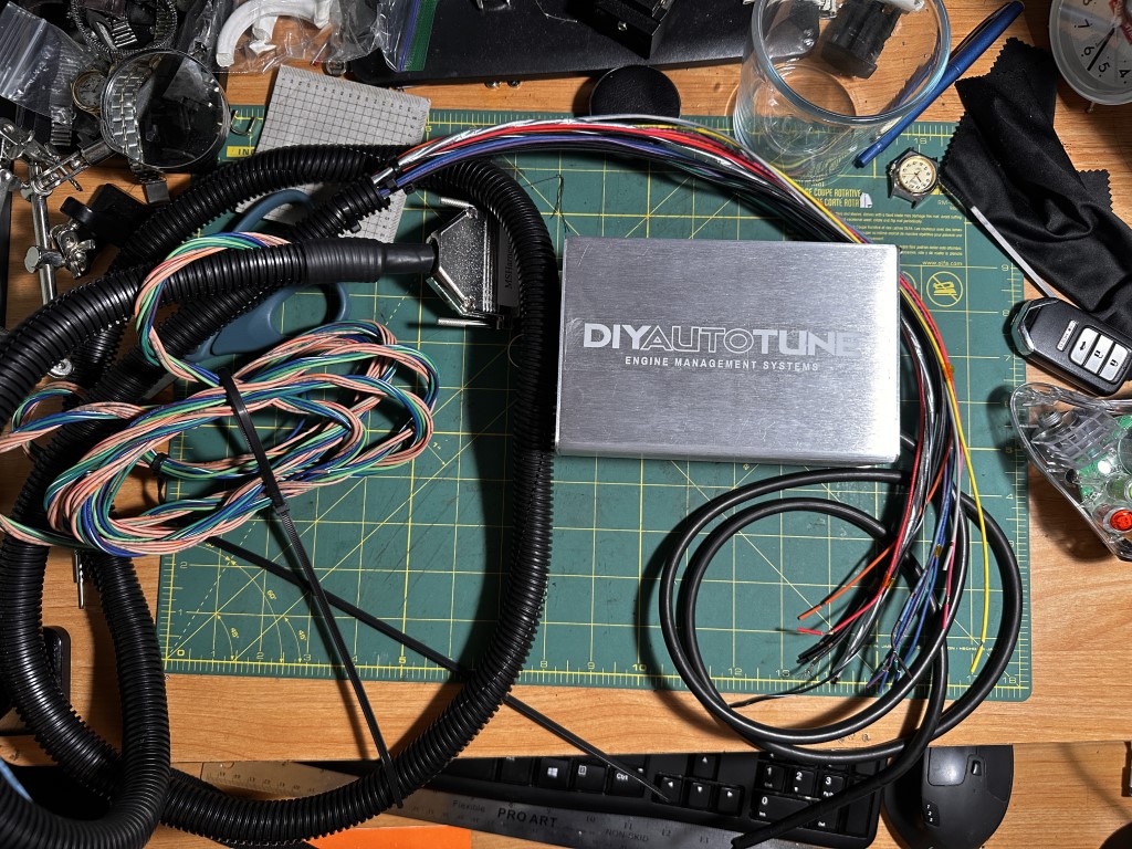
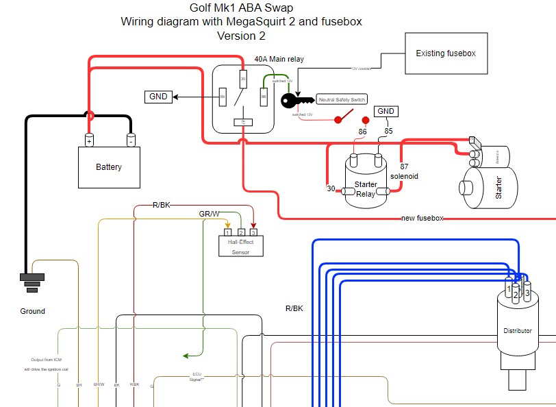
The silly journey to put EFI on a 100HP car. This is the Cabby’s EFI conversion project I’ve worked on for the last six months, so let’s dive into the ECU and wiring.
Quick links. TLDR: here’s the wiring diagram and parts list.
What is a MegaSquirt ECU? The ultimate DIY ECU
A car’s ECU is the computer that tells it when to spark and when to squirt fuel based on various data inputs from the engine and environment. It’s not magic, it’s science. Specifically, the MegaSquirt (MS) ECU is a cheap, DIY alternative to other aftermarket ECUs to make standalone setups more accessible. For about $650, with a wiring harness and test kit, I got my ECU setup ready to go in a couple days. In the nature of DIY, if you don’t know what you are doing, like me, there are A LOT of “ifs” and situational aspects in the MegaSquirt setup, and it can take a lot of work to figure out what you want to do. But with time and determination, you can work through the MS ECU.
Below is the original diagram provided by MegaSquirt. There are several versions of this diagram, depending on the version and generation of MS, so this may be different than the ones you could have seen before. The diagram illustrates what the ECU will read (inputs) and what it will control (outputs). With this control on inputs and outputs (I/O), we can tune the engine to behave how we want it to.
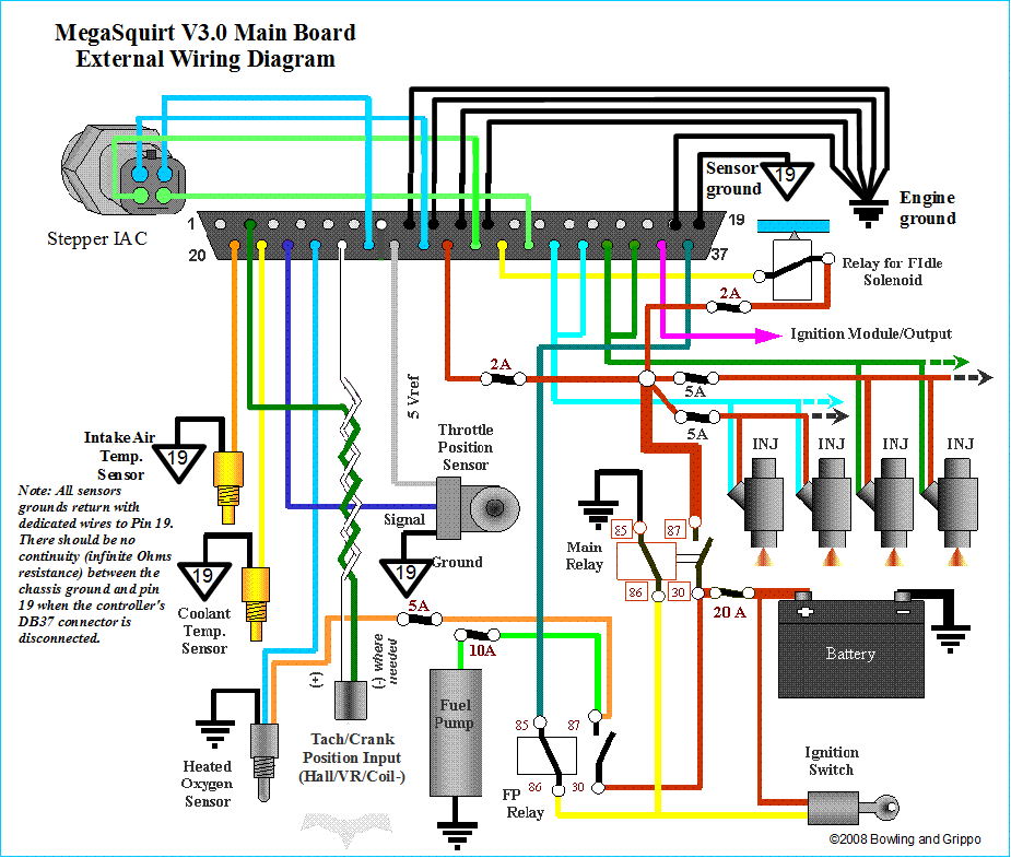
The sensor data read by the ECU will read off a table of values and spit out some value to spray a certain amount of fuel and spark at a specific time also known as a fuel map, this allows the ECU to dynamically adjust the car’s fueling.
The ECU has a DB37 connector with 37 possible pins to give and retrieve instructions. Here’s the wiring diagram provided by Megasquirt, this is a good place to get started with your own map.
Wiring Diagram for Megasquirt II V3.0
- Wiring diagram here or copy and paste the following link:https://drive.google.com/file/d/1PKhUPFUTe5xEFgeondNXi2kL-YfknbU5/view?usp=sharing.
This table references the terminals for the DB37 connector on the MegaSquirt 2 for a Golf ABA 2.0L engine using the following sensors. More info can be found in the Sensors section.
- MS2 On-board MAP sensor to manifold
- GM Intake Air Temperature sensor
- ABA Engine Coolant Temperature sensor
- Honda CBR 600RR throttle position sensor
- AEM Wideband X-Series O2 Sensor
- ABA VR Sensor
Megasquirt Wiring Table
Here’s a wiring table of what I’m going to use for my DB37 harness. I will remove wires as needed.
| Terminal or Pin | Color | Used? | Function | IN/OUT | Max Amps |
|---|---|---|---|---|---|
| 1/2/24 | 🛡️⚫ Black in Shield | YES | Crank sensor ground | GND | - |
| 2/1/24 | 🛡️ Shield | YES | Crank sensor shield | GND | - |
| 3 | Tan | NO | CAN High | (Comms) | - |
| 4 | Tan/Red | NO | CAN Low | (Comms) | - |
| 5 | Tan/Green | NO | - | - | - |
| 6 | Tan/Orange | NO | - | - | - |
| 7 | ⚫⚪Black/White stripe | YES | On-board sensor ground for, IAT, ECT, TPS | GND | - |
| 8 | - | NO | Spare GND | GND | - |
| 9 | - | NO | Spare GND | GND | - |
| 10 | - | NO | Spare GND | GND | - |
| 11 | - | NO | Spare GND | GND | - |
| 12 | - | NO | Spare GND | GND | - |
| 13 | - | NO | Spare GND | GND | - |
| 14 | - | NO | Spare GND | GND | - |
| 15 | ⚫ Black | YES | Sensor ground, High current power ground | GND | - |
| 16 | ⚫ Black | YES | Sensor ground, High current power ground | GND | - |
| 17 | ⚫ Black | YES | Sensor ground, High current power ground | GND | - |
| 18 | ⚫ Black | YES | Sensor ground, High current power ground | GND | - |
| 19 | ⚫ Black | YES | Sensor ground, High current power ground | GND | - |
| 20 | 🟠 Orange | YES | Intake air temperature (IAT) | In | - |
| 21 | 🟡 Yellow | YES | Coolant temperature sensor/Engine Coolant Temperature (ECT) | In | - |
| 22 | 🐋 Light Blue | YES | Throttle position sensor (TPS) | In | - |
| 23 | 🎀 Pink | YES | Exhaust Oxygen Sensor (EGO or O2) | In | - |
| 24/2/24 | 🛡️⚪White in Shield | YES | TACH IN | In | - |
| 25 | Blue/White | NO | IAC1A | (Out) | - |
| 26 | 💿 Gray | YES | TPS 5V Supply | Out | 0.5A |
| 27 | 🔵🔴 Blue/Red | NO | IAC1B | (Out) | 0.1A |
| 28 | 🔴 Red | YES | 12V Supply | In | 0.5A |
| 29 | 🟢Green/White | NO | IAC2A | (Out) | <1A |
| 30 | 🍏 Light green | YES | PWM Idle (Fan control) | Out | 0.1A* |
| 31 | 🟢🔴 Green/Red | NO | IAC2B | (Out) | 0.5A |
| 32 | 🔵 Blue | YES | Injector Bank 1 | Out | 7A |
| 33 | 🔵 Blue | YES | Injector Bank 1 | Out | 7A |
| 34 | 🟢Green | YES | Injector Bank 2 | Out | 7A |
| 35 | 🟢Green | YES | Injector Bank 2 | Out | 7A |
| 36 | 🟤 Brown | YES | Ignition signal out | (Out) | 7A |
| 37 | 🟣 Violet | YES | Fuel pump relay output | Out | 0.1A |
Deutsch bulkhead connector

A bulkhead connector! I’ve wanted to do a bulkhead because it was what all the racecars had. It looks sick, and as far as reliability and durability are concerned, provides a solid bang for your buck. I was even more excited to learn that it would cost me less than $150 in parts. Wiring and putting together connectors is easy, but the hard part is parts availability and planning.
- Deutsch HDP2Bulkhead 29-pin Conector kit, 12-16-20 AWG Solid Contacts
- Cheap Deutsch crimper, 14, 16, 18 gage
- Cheap Deutsch crimper, 20 gage
It’s a challenge in planning and wiring that I wanted to take to prepare myself for future wiring jobs. Crimping the MS2 harness directly to my components would be simpler, but a bulkhead connector would make it easier to service in the long run. Automotive wiring is a challenge for most people, and if I can show others that putting in the time and work will pay dividends in the build’s reliability, consistency, and durability. Mapping the diagram forces me to consider every wire going into my car and makes me understand what I’m doing.
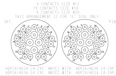
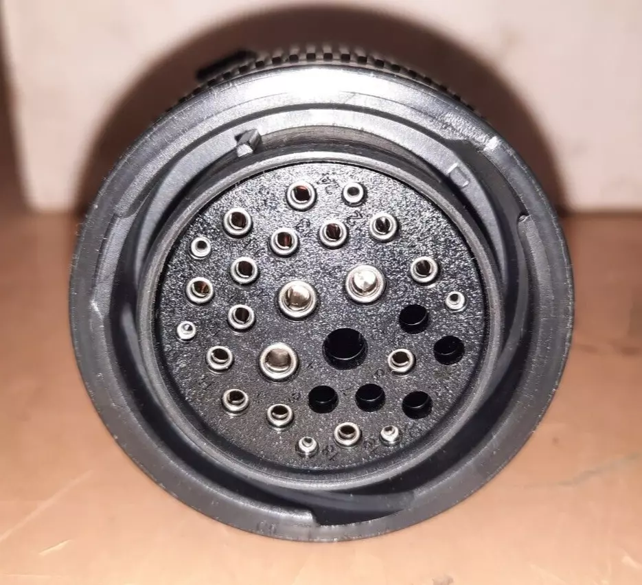
Bulkhead firewall (plug) pinout
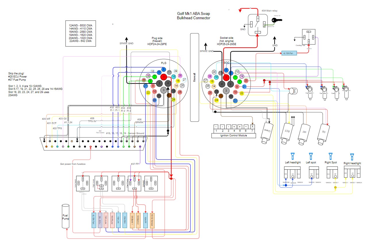
Let’s take the wires from the MS2 harness and put it into the bulkhead connector. Since we know how many wires we want to use, I decided on the 29-pin connector. The table below shows the pins I’m using and what function from the MS2 or secondary fusebox it will provide. Find out what wire you want and if you plan to use wire splices.
View the like bulkhead diagram here or visit https://app.diagrams.net/#G1PKhUPFUTe5xEFgeondNXi2kL-YfknbU5
Bulkhead Deutsch HDP29 connector wiring table
| Pin | MS2 Function | Color | Fusebox | AWG | Splice CMA |
|---|---|---|---|---|---|
| 1 | Fusebox | 🔴 Red | Fusebox power | 12-14 | |
| 2 | Fusebox | ⚫ Black | Spare Ground | 12-14 | |
| 3 | - | ||||
| 4 | Sensor engine ground OUT, DB37/15-19 | ⚫ Black | - | CRIMP | Yes, 6480 CMA |
| 5 | ⛽Injector 1, DB37/32 | 🔵 Blue | - | 20 | |
| 6 | ⛽Injector 2, DB37/33 | 🔵 Blue | - | 20 | |
| 7 | ⛽Injector 3, DB37/34 | 🟢 Green | - | 20 | |
| 8 | ⛽Injector 4, DB37/35 | 🟢 Green | - | 20 | |
| 9 | Fusebox | 🔴 Red | Bank 1 power, Fusebox Bank 1 | 20 | |
| 10 | Fusebox | 🔴 Red | Bank 2 power, Fusebox Bank 2 | 20 | |
| 11 | ⚙️Crank sensor ground, DB37/1 | ⚫ Black | - | 20 | |
| 12 | 💥Ignition Out, DB37/36 | 🟤 Brown | - | 20 | |
| 13 | Sensor ground IN (ECT-, TPS-, IAT-, O2-), DB37/7 | ⚫ Black | - | 20 | Yes, 6480 CMA |
| 14 | 💨IAT IN, DB37/20 | 🟠 Orange | - | 20 | |
| 15 | 💧ECT IN, DB37/21 | 🟡 Yellow | - | 20 | |
| 16 | 🎿TPS Signal IN, DB37/22 | 🐋Cyan | - | 20 | |
| 17 | ⚡TPS 5V Supply, DB37/26 | 💿 Grey | - | 20 | |
| 18 | - | ||||
| 19 | 🌫️Fan control, DB37/30 | 🍏 Light green | - | 20 | |
| 20 | - | ||||
| 21 | Fusebox | 🔴 Red | Headlight Left low beam | 18 | |
| 22 | Fusebox | 🔵 Blue | Headlight Right low beam | 18 | |
| 23 | Fusebox | 🟡 Yellow | Headlight Left high beam | 18 | |
| 24 | Fusebox | 🔵 Blue | Headlight Right high beam | 18 | |
| 25 | Fusebox | 🟡 Yellow | O2 Sensor Power | 18 | |
| 26 | unused | 🔴 Red | Fan relay power | 18 | |
| 27 | unused | ||||
| 28 | 💨O2 Signal IN, DB37/23 | 🎀 Pink | - | 18/20 | |
| 29 | unused |
The Deutsch Contact Size and you
Here are four things to consider when choosing your connectors:
- What size pin or socket?
- You need both the pin and the socket. This creates the wire connection, and the type of pin or socket depends on the connector you have. Refer to the specification (Deutsch stamped contacts) on what contact size you need. There are two types of terminals: stamped and solid. Stamped ones are cheap. Solid contacts are a pricy but durable option.
- What size AWG are you using?
- Deutsch contact sizes is NOT ALWAYS equal to the exact AWG size. You will see size 12, 16, and 20 contacts, but they come in various AWGs, so there is some flexibility in the wire that you can use. Because of this flexibility, price and availability come into play. You need to know what size wires you are using. In my case, I am using AWG 12, AWG 18, and AWG 20. AWG 12 is for high-power applications like the main relay and fans, while AWG 18-20 is for low-power applications like the ECU, injectors, and sensors.
- What material?
- There are multiple to choose from. Consider Gold (Au), Nickel (Ni), Tin (Sn), and Silver (Ag). Let’s focus on the most common ones, Gold and Tin. According to this Molex article, essentially, gold connectors are more durable than tin, maintain a durable connection over time and never mix the types of connectors while tin connectors are cheaper, do the job, but may not survive many mating cycles. Tldr; buy what’s available and never don’t mix mating materials. Tin is cheap. Gold is highly reliable. Some connectors may be made of both (AU/SN).
- Make sure that the pins and sockets are of the same materials when buying your parts. There are gold (Au), tin (Sn), nickel (Ni), and silver (Ag)
- Is it available to buy?
- Availability is the bane of car parts. The parts exist, but your job is to find out who sells them and who has them for the cheapest price. Tl;dr: If a kit exists, buy the kit. Hunting for the same part after the fact will ruin your future days.
Splicing wires with CMA

Bare-metal wire splices were introduced to me by this article from High Performance Academy. The biggest benefit is that you can ACTUALLY SEE the splice. The issue with butt splicers is that it is shrouded in insulation that you cannot 100% check reliability of the splice. Solder connectors also work, but you also run the risk of solder cracking. Without the extra insulation, the crimps are much smaller and don’t make a harness too bulky. Lastly, open barrel splices make it simple to splice multiple wires together without too much issue.
These crimps can be harder to use because it is much smaller, but the advantage to these open-barrel types is that it doesn’t include insulation and lets me see the wires physically spliced with a good connection without having to guess when putting them into a butt connector.

As we splice more wires together, we want to add them up, and then we can choose a splice. Below are the available splices.
| Splice size | CMA |
|---|---|
| Small TE 62759-1 | <1500 |
| Medium TE 63130-2 | 1500-5000 |
| Large TE 62357-1 | 5000-10000 |
- 1500 CMA and less of combined wire area: TE 62759-1 These are SMALL. Best for 22AWG or higher.
- 1500 to 5000 CMA of combined wire area: TE 63130-2 Example: Two 20AWG wires or two 18AWG wires for ECU crimping.
- 5000 to 10,000 CMA of combined wire area: Example: One 14AWG wire to four 20AWG wires for fuel injector wires.
Reference table of AWG and its relative CMA
| Wire size (AWG) | CMA |
|---|---|
| 12 | 6530 |
| 14 | 4110 |
| 16 | 2580 |
| 18 | 1620 |
| 20 | 1020 |
| 22 | 642 |
Bulkhead receptacle (the hot socket side)
Part number: HDP24-24-29SE-L017
Housing for Female Terminals, Wire-to-Wire, 29 Position, Sealable, Black, Wire & Cable, Power & Signal, Panel Mount, Hybrid. THIS USES THE SOCKET PINS.
The receptacle, socket or otherwise known as the female end of the connector, is where we’ll connect the Megasquirt harness. This will be routed in the car and then mounted on the firewall. As a tip from TE Connectivity, use the socket side as the hot side (the one connected to the battery) so you don’t shock yourself. Much harder to cause a short with holes than prongs.
THESE ARE THE SOCKET PINS.
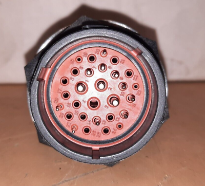
Bulkhead Plug (the cold pokey side)
Part number: HDP26-24-29PE-L017 Housing for Male Terminals, Wire-to-Wire, 29 Position, Sealable, Black, Wire & Cable, Power & Signal, Panel Mount, -67 – 257 °F [-55 – 125 °C], Hybrid
This will be on the engine bay side that will connect all of our connectors, sensors, injects, and engine bay relays. This should be unpowered (cold). THIS USES THE POKEY PINS.
Bulkhead Parts list
| Item | Image | Description | Part Number | Quantity | Subtotal |
|---|---|---|---|---|---|
| Deutsch HDP2Bulkhead 29-pin Connector kit, 12-16-20 AWG Solid Contacts |  |
Bulkhead kit | 1 | $80 | |
| Deutsch socket | 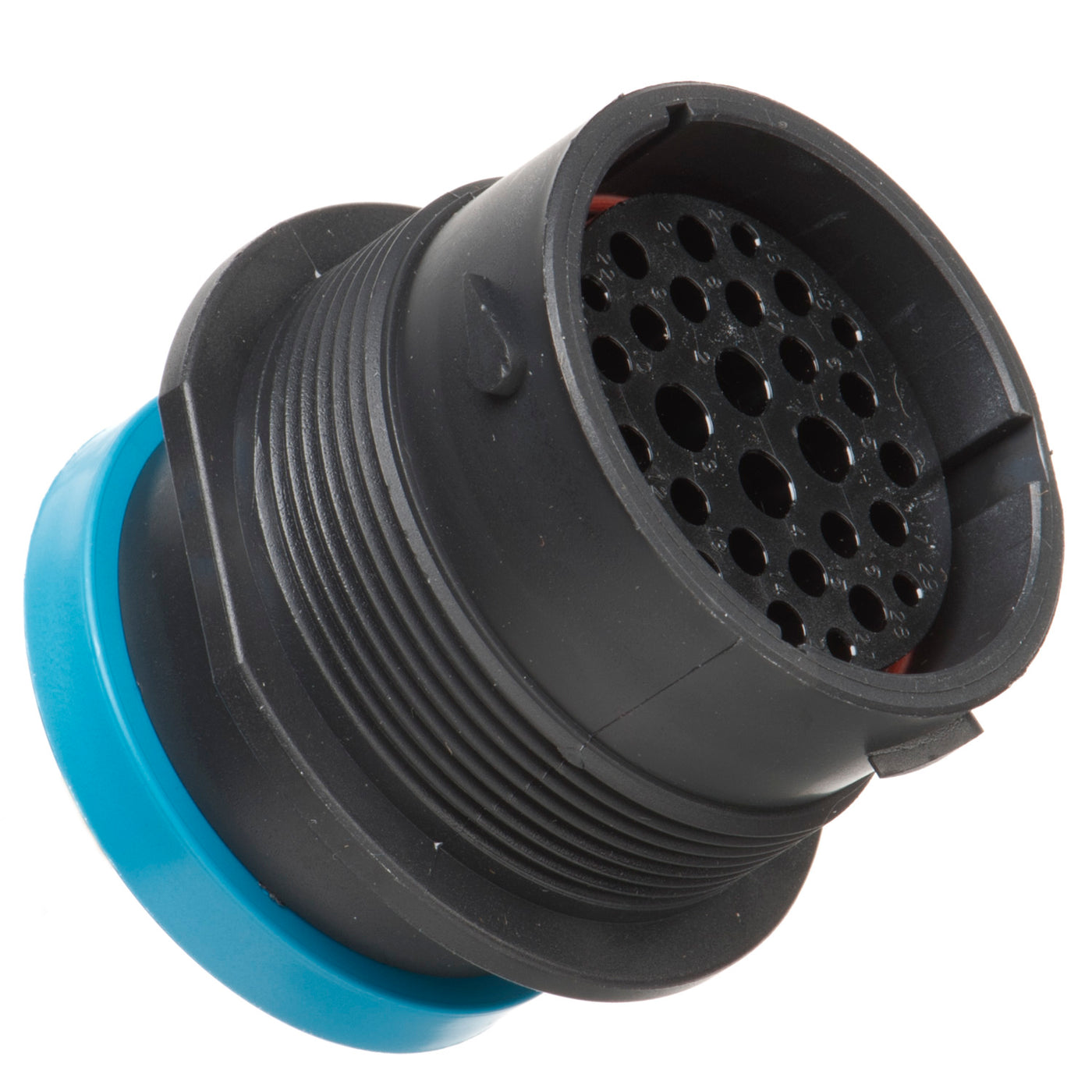 |
Bulkhead plastic socket, 29-pin | HDP24-24-29SE-L017 | 1 | |
| Deutsch plug, | 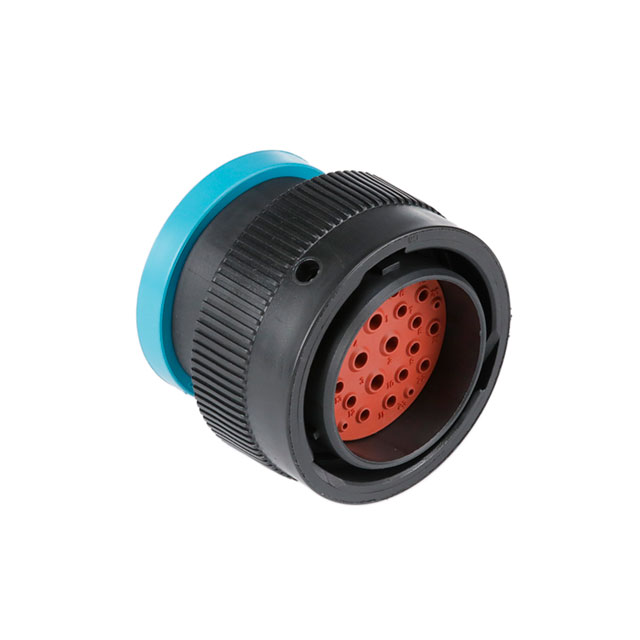 |
Bulkhead plastic plug, 29-pin | HDP26-24-29PE-L017 | 1 | |
| Medium splice | 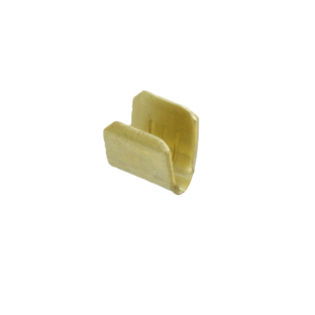 |
Splices for my 18-20AWG | 63130-2 | 100 | $8.52 |
| Large splice | 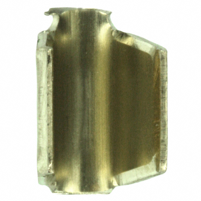 |
Splices for my 14AWG | 62357-1 | 100 | $11.25 |
| Size 12 Solid Receptacle pin (female) | 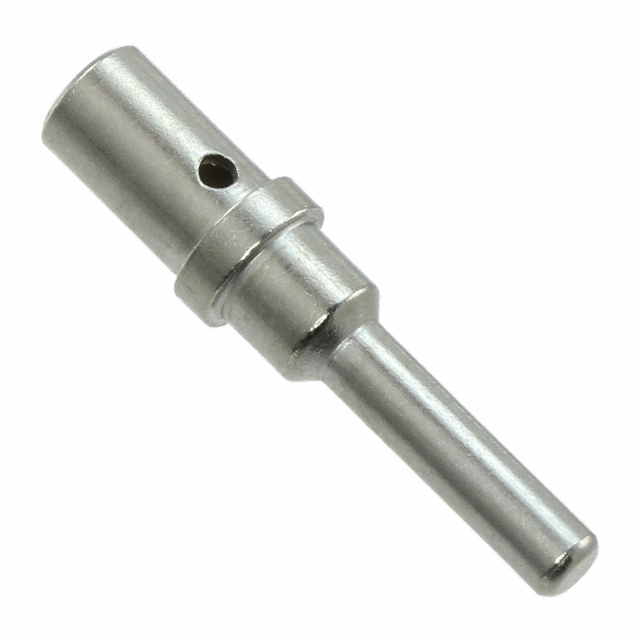 |
(1060) 0460-XXX-12 | |||
| Size 12 Solid Plug pin (male) | 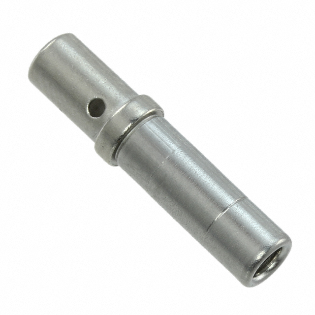 |
(1062) 0462-XXX-12 | |||
| Size 16 Solid Receptacle pin (female) | |
(1060) 0460-XXX-16 | |||
| Size 16 Solid Plug pin (male) |  |
(1062) 0462-XXX-16 | |||
| Size 20 Solid Receptacle pin (female) | 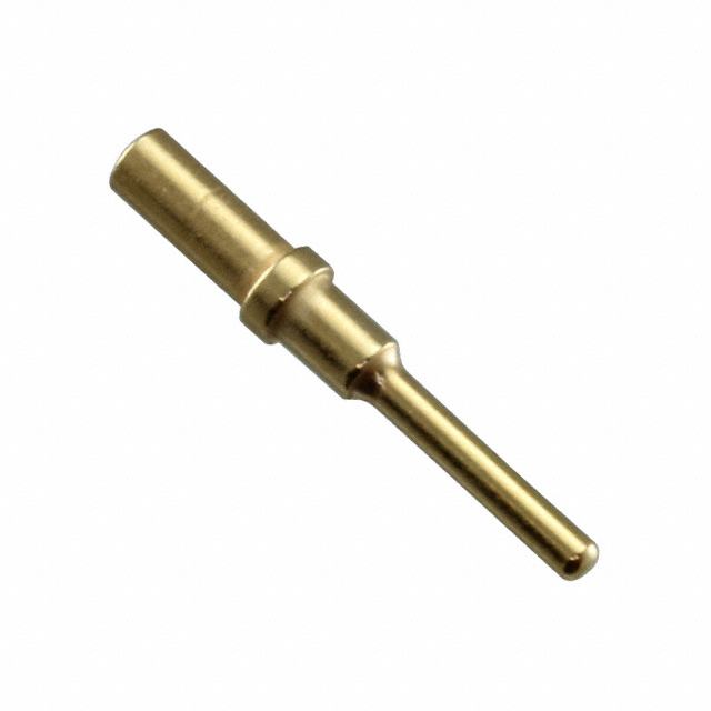 |
16-20AWG, Gold, 0460-202-1631 | (1060) 0460-XXX-20 | ||
| Size 20 Solid Plug pin (male) | 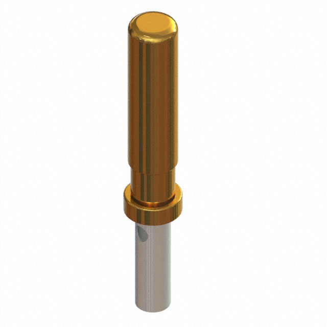 |
16-20AWG, Gold, 0462-201-1631 | (1062) 0462-XXX-20 | ||
| Boot |  |
Protective boot | HD30-24BT-BK | 2 | $3.07 |
| Fuse holder with terminals | 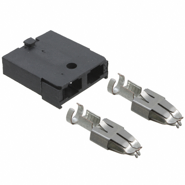 |
Individual fuse holder | DigiKey, F5194-ND |
Fuse and relay panel
 The history of Golf Mk1/Mk2 and Polo rallies has always attracted me from my short time playing Dirt Rally 2.0. This is optional for most builds, but the Golf Mk1 factory wiring is tired, so I’m rewiring some things for reliability.
I couldn’t find any fuse box I liked, so I’m making a custom-mounted one. Using individual fuse holders, 178.6152.0001, I’ll mount the fuse holders behind an ABS faceplate and mount the fuses like the ones above. I might update this to include more goodies (AHEM on-board rally intercom).
Wire Sizes
Provided by the MegaManual, here is a list of wire sizes recommended for the correct amperage for about 15 feet. The sizes in bold are the ones I normally use.
| Wire Size for Runs up to 15 Feet | Length | Current |
|---|---|---|
| Gauge | Metric | Amps |
| 8 | 8.0 | 32-40 |
| 10 | 5.0 | 28-35 |
| 12 | 3.0 | 18-30 |
| 14 | 2.0 | 12-20 |
| 16 | 1.0 | 8-13 |
| 18 | 0.8 | 6-10 |
| 20 | 0.5 | 4-6 |
| 22 | 0.22 | 2-3 |
| (capacity depends on wire quality & length of run) |
Sensors
Sensors give the ECU data so that it can do its job. If a sensor fails or malfunctions, the ECU will bug out and use some default value. Do your homework and plan if failure happens. From my experience with parts, you get what you pay for. While eBay and Alibaba sensors might come cheap, I wouldn’t count on all of them giving you all of the correct instructions and wiring diagrams needed to do the work. Stick to the tried and true sensors like OEM, GM, or other brand names like Bosch or Denso sensors.
Sensors work as a result of changing their physical properties to produce some resistance and that resistance will reference a specific value. It can be a bi-metallic metal, plate, resistance, and so on. Remember, sensors grounds should end at the engine, not at the battery. Grounding to the engine usually will collect less noise than grounding at the battery. Grounding at the battery may collect noise from other electronics. Use the next table to check off focus on what sensors you will need. Otherwise, read along.
Table of sensors for MegaSquirt 2
| Sensor | MS Pin# | MegaSquirt Wire Color | Ground | Connection | Existing or Buy | Part Name or Number | # Total wires | Wires |
|---|---|---|---|---|---|---|---|---|
| Manifold Absolute Pressure (MAP) | none | none | none | 1/8” vacuum line | Existing, on-board MS | MPX4250 | none | none |
| Intake Air Temperature (IAT) | 20 | Orange | Black White DB37/7 | 3/8” NPT | Buy | GM IAT 25036751 | 2 | 5V, Signal |
| Engine Coolant Temperature (ECT) | 21 | Yellow | Black White DB37/7 | Four wire: 2 are ground, 1 PCM (ECU IN), 1 to gauge sender | Existing | VW 357 919 501A | 4 | Ground, signal, Ground, temp gauge |
| Throttle Position (TPS) | 22 | Light Blue | Black White DB37/7 | Honda TPS | Buy (on ITBS) | Honda 255478286857 | 3 | Ground, 5V, signal |
| Exhaust Gas Oxygen (O2 or EGO) | 23 | Pink | ECU | AEM 30-3427 | Existing | AEM 30-0300 | 6 | Multiple, splice only |
| Ignition (VR) | 24 | White/Shield | Black DB37/1 | ICM/6, replace existing Hall-Effect signal | Existing | VW 021 907 319A | 3 | Ground, Power, shield |
MS2 On-board MAP sensor to manifold
Part: MPX4250 2.5 Bar MAP Sensor
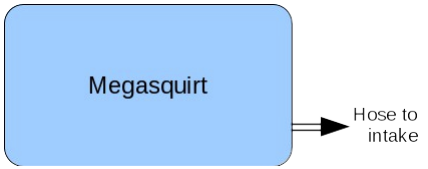
The onboard MAP sensor is connected with a 1/8” vacuum hose to any vacuum port on the intake manifold. Air pressure is one way for the ECU to see engine load. More pressure means more load. Turbo or supercharger? You’re going to need this. For naturally aspirated, it’s a very good helper. You’ll have something like this for NA with a big plenum. For ITBS, it depends if you’re planning to incorporate MAP with your alpha-n tuning, but doesn’t hurt to add.

Read more about how the sensor works here: https://www.nxp.com/docs/en/data-sheet/MPX4250D.pdf. There is no pinout because it’s already integrated on the ECU. If you’re not using this type of sensor, follow your specific part diagram.
GM Intake Air Temperature sensor
Part: 25036751
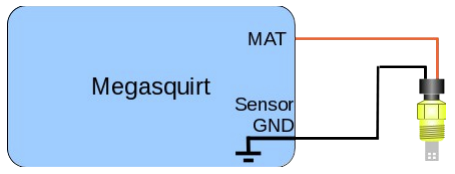
The GM IAT is a universally accepted sensor that most aftermarket users will opt for if they don’t already have an IAT sensor. The sensor only has two pins, sensor ground and temperature signal. Place the sensor in the intake manifold or plenum, wherever your car gets air.

Table: Intake Air Temperature (IAT) Sensor pinout
Part: GM 25036751
| IAT Sensor Pin | MegaSquirt ECU Pin |
|---|---|
| 1 Signal ground | Black White DB37/7 |
| 2 Temperature signal | Orange DB37/20 |
Table: Intake Air Temperature (IAT) expected temp resistance values
| Intake Air Temperature Temperature | Ohms |
|---|---|
| 48F | 7000 |
| 87F | 1930 |
| 146F | 560 |
ABA Engine Coolant Temperature sensor
Part: Golf MK3 ECT black body yellow ring, 357 919 501A
Related part: Engine cooling fan switch (AC switch) 2-pin, 191 919 369A
What does the Coolant Temp Sensor do?
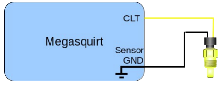
Measure resistance between pins 1 and 3 at three different temperatures, use this to map temperature curve. Pin 2 and 4 provide a temp readout to our gauge readout.

Table: Electronic Coolant Temperature (ECT) Sensor pinout
Part: Golf MK3 ECT black body yellow ring, 357 919 501A
| ECT Sensor Pin | MegaSquirt ECU Pin |
|---|---|
| 1 Black White Signal ground | Black White DB37/7 |
| 2 Brown Blue Ground to block | – |
| 3 Blue Signal ECU | Yellow DB37/21 |
| 4 Blue Dash gauge | – |
Table ECT expected temp resistance values
| Temperature | Ohms |
|---|---|
| 88F | 1880 |
| 87F | 1930 |
| 146F | 560 |
Honda CBR 600RR throttle position sensor
Part: HONDA 255478286857 Connector: Compatible with Sumitomo HX 040 6189-0887 receptacle

The ECU supplies the sensor with voltage and ground and completes a circuit. The sensor houses a potentiometer, a resistor that changes with position. The TPS is mounted on the throttle linkage and moves with the throttle plates. As the throttle plate opens and closes, the resistance changes and is sent as an output (pin 3). The ECU reads the voltage and digitally tells the ECU the throttle is at the x position.
Table: Throttle Position Sensor (TPS) pinout
Part: HONDA 255478286857
| TPS Sensor Pin | MegaSquirt ECU Pin |
|---|---|
| 1 TPS VREF (voltage reference) | Grey DB37/26 |
| 2 Sensor ground | Black White DB37/7 |
| 3 TPS Signal | Blue DB37/22 |
AEM Wideband X-Series O2 Sensor
Part: AEM 30-0300 X-Series Wideband UEGO Sensor, AEM 30-0300
Harness: AEM 30-3427
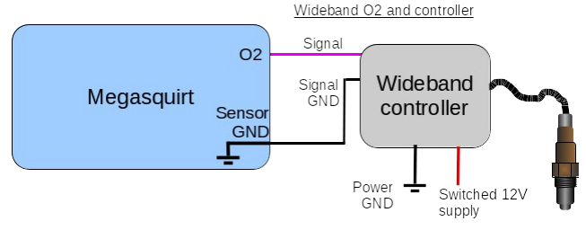
Table: Exhaust Gas Oxygen Sensor (EGO) or O2 pinout
| O2 Sensor Pin | MegaSquirt ECU Pin |
|---|---|
| 1 Signal ground | Black White DB37/7 |
| 2 Ground to block | – |
| 3 Signal ECU | Yellow DB37/21 |
| 4 Dash gauge | – |
Idle Air Control (not using IAC)
In my case, idle will be handled by a warm-up enrichment and wax idle mechanical enrichment on the ITBS.
This means:
- No stepper IAC
- No PWM IAC
- Ignore the following:
- IAC1A, DB37 pin 25
- IAC1B, DB37 pin 27
- IAC2A, DB37 ping 39
- IAC2B, DB37 pin 31
- S12C to JS9
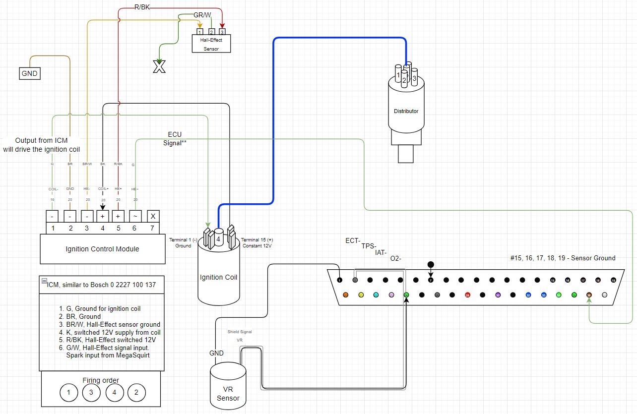
ABA VR Sensor and the Volkswagen Golf MK1 Ignition Control Module
Part: ABA VR sensor, 021 907 319A
Part: Golf MK1 ICM, VW part 191 905 351
Part: Ignition coil, VW part 1 220 522 016
Okay, so ignition is probably the most complicated and important section in any engine setup with an aftermarket ECU. Every setup is going to be slightly different, so use this as a guide to get started.
More info on 3 wire VR sensor from Volkswagen

Table: Variable Reluctance (VR) Sensor pinout
Part: ABA VR sensor, 021 907 319A
| VR Sensor Pin | MegaSquirt ECU Pin |
|---|---|
| 1 Signal | White DB37/24 |
| 2 Sensor ground | Black DB37/1 |
| 3 Shield | SHIELD DB37/2 |
How it works
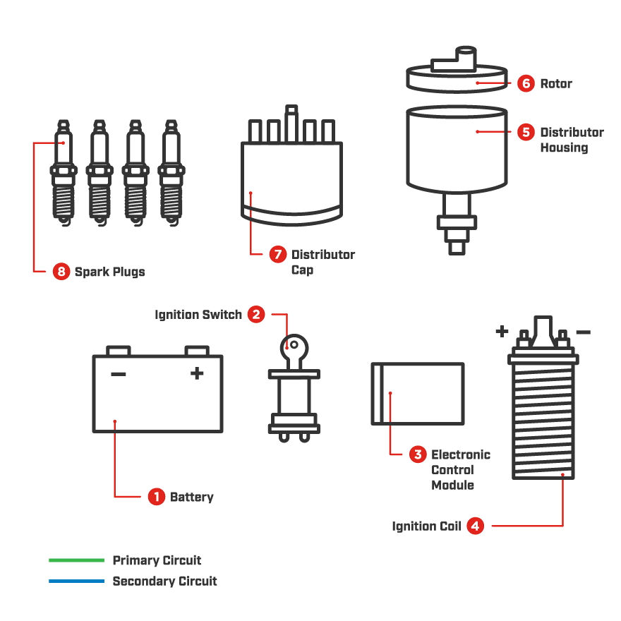
Champion Auto Parts digram, note the primary and secondary circuits at https://www.championautoparts.com/Technical/Tech-Tips/How-Ignition-Systems-Work.html
- Battery is properly wired
- Ignition switch provides power to ECM
- ECM is powered on
- ECM provides grounding signal (via engine) to ignition coil
- Distributor housing receives primary discharge
- Rotor rotates to correct point
- Distributor cap completes the circuit from coil to spark plug
- Discharge spark into cylinder
When the engine turns, we can infer that our crankshaft and crank trigger wheel are moving. The VR sensor reads the crank trigger wheel, where the signal is interrupted by the missing tooth (usually). This change is seen by the ECU. Unlike the original configuration which uses the hall effect with a trigger window in the distributor to mark the spark events. The VR signal to tell MegaSquirt to control the spark.
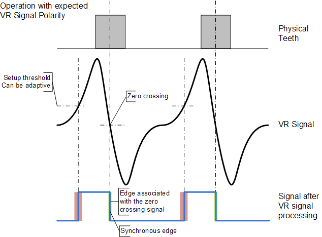
We use signal input from the VR sensor and connect it to ECU #24 TACH IN. MS2 will read the AC sine wave and convert it into a 5V DC square wave, which will finally output through IGN signal (#36 IGN OUT) to the ICM. The ICM will trigger spark in the distributor and allow combustion.
The ICM will ground the ignition coil’s primary winding, collapsing the magnetic field and produce the high voltage spark at the secondary winding to the distributor, and finally, sending the spark to our spark plug.
ABA Megasquirt Trigger wheel setup
We control the ABA by reading the incoming signal from the 60-2 trigger wheel and a VR sensor.
- The ABA uses 60-2 missing tooth wheel attached to the crank; this is the CRANK(VR) sensor to #24 TACH IN
- Single ignition coil; MEGA #36 IGN to the Ignition Control Module (ICM); refer to amplifiers
- The ignition signal (VR conditioned) Golf ICM gets actuated by ignition signal; spark event to distributor
- Distributor spark to spark plug
Tuner Studio settings
- Toothed Wheel:
- Physical wheel: missing tooth on crank
- Trigger Angle/Offset: always zero
- Angle between main and return: n/a
- Secondary wheel: none
- Main wheel speed: Crank
- 2nd trig every rotation of: n/a
- GM HEI/DIS options: n/a
- 420A/NGC alternate cam: n/a
- Use cam signal if available: n/a
- Ignition input capture:
- Spark output
- Number of coils: 1
- Spark hardware in use
- Cam input
- Trigger wheel arrangement: single wheel with missing tooth
- Trigger wheel teeth: 60
- Missing teeth: 2
- Tooth #1 angle:
- Main wheel speed: crankshaft
- Second trigger active on: no dual wheel
- Level for phase 1: no dual wheel
- And every rotation of: no dual wheel
- Trigger
- Trigger Angle: 82-90
- 0 offset (for VR systems)
- Trigger A: 5
- Trigger return A: 14
- Trigger B: 35
- Trigger Return B:44
- TDC at 14th tooth; 84 degrees
- Single coil and distributor
- Ignition Input Capture to ‘Rising Edge’ or other way if you wired the VR sensor opposite
- Cranking Trigger to ‘Trigger Return’
- Coil Charging Scheme to ‘Standard Coil Charging’
- Spark Output to ‘Going Low (Normal)
In-depth on ignition wiring for the Bosch 137 module
This is the theory behind the ignition system. I haven’t officially tested it yet since the engine is still out of the car, but it will probably work for the 60-2 configuration. We can control ignition by tapping into the existing ICM, and The Golf’s Ignition Control Module (ICM) is as follows:
| Golf MK1 ICM Pin | Function |
|---|---|
| 1 | ground for ignition coil |
| 2 | ICM Ground |
| 3 | Hall-Effect sensor ground |
| 4 | 12V for ignition coil |
| 5 | Hall-Effect sensor 12V |
| 6 | Hall-Effect signal |
| 7 | –unused– |
Since we don’t depend on the HE sensor to get a signal, we swipe that pin and use the MegaSquirt ignition output. Again, MegaSquirt will condition the VR sin wave into the expected (Hall-effect) square wave.
| Hall-Effect (HE) and MK1 ICM Pin | Function | Hall-Effect (HE) and ICM Pin | Function | |
|---|---|---|---|---|
| HE Sensor/1 | GND HE | HE Sensor/1 | GND HE | |
| HE Sensor/2 | Signal | HE Sensor/2 | - | |
| HE Sensor/3 | Power | HE Sensor/3 | Power HE | |
| ICM/1 | GND Coil | ICM/1 | GND Coil | |
| ICM/2 | GND ICM | ICM/2 | GND ICM | |
| ICM/3 | GND HE | ICM/3 | GND HE | |
| ICM/4 | 12V Coil | ICM/4 | 12V Coil | |
| ICM/5 | 12V HE | ICM/5 | 12V Hall-Effect Sensor | |
| ICM/6 | Signal HE | ICM/6 | DB37/36 IGN OUT | |
| ICM/7 | Unused | ICM/7 | Unused |
My VW Golf mk1 ICM, I’m assuming (lol), should be an intelligent module and have dwell settings implemented, otherwise known as closed-loop control of dwell. The module will automatically adjust the dwell settings based on current. Going off of a reference here, my car did not come with a separate ECU, therefore dwell must have been controlled within the model known as Auto-dwell. Auto-dwell is superior in that it won’t break your shit, usually.
WTF is auto-dwell and why does that matter to me? How NOT to fry your ignition module
Dwell is the time it takes for a coil to produce the spark for a spark plug. If we shorten the dwell time too much, the primary winding does not get enough charge-up time, and the spark is weak and shitty and your engine runs rough. Basically, if we extend the dwell too long, the primary winding charges too much and can cause overheating and frying the coil.
According to this article, “dwell, or ‘dwell time’ in ignition systems refers to the period that the coil is on, i.e., that current is flowing through the primary winding and the magnetic field is building up in the coil.”
In addition, dwell angle is the dwell time measured in degrees of rotation, which refers to distributor setups where the rotor and contact points are closed, creating the spark event.
The Bosch 137 module seems to be cross-listed with the VW part 191 905 351, which is what we have. The 137 is like the 139 module in that it’s smart and dynamically sets the dwell settings for us. Without needing to set dwell, we don’t have to worry too much about having a shitty spark or cooking our coil. So, we can use these settings in TunerStudio according to DIY AutoTune.
Ignition references
- How to MegaSquirt your Water Cooled VW
- Trigger offset = 60 (this will vary, depending on the distributor orientation; see notes at the end of the article)
- Ignition Input Capture to ‘Rising Edge’
- Cranking Trigger to ‘Trigger Return’
- Coil Charging Scheme to ‘Standard Coil Charging’
- Spark Output to ‘Going Low (Normal)
Read more:
-
- Bosch 0 2227 100 137 This is very similar to the 124, but the spark input signal is on pin 6.
-
Using MSII to control the xxx 13modules
- 137 Triggers when it’s grounded, i.e. from falling edge.
-
- “Yes, a Bosch 137 ‘smart dwell’ module together with one Volvo coil (COP type)”
-
Bosch Ignition Modules components
- Max primary current, 8-10A
- Type of trigger, Hall effect
-
Dwell on TCi ignition, smart dwell
- However I think I located enough listings that I believe to be correct and came to the conclusion the ICM is in fact the same between the “knock box” and “non-knock” ignition systems for that period of VWs. Ha-ha, all of that to find out its the same. The current part number that I believe to be the correct ICM is: Bosch= 227.100.137, and VW= 191.905.351.B.
-
- it is labeled ‘Hall Efect Module”. Pin 6 is the input, Pin 5 is a 12V supply for a hall sensor and pin 3 is signal ground for the hall sensor if you wire your hall sensor supply to the module instead of MS.
-
How to tell if a Bosch ignition unit does dwell
- As far as I’m away the built-in dwell modules were only used standalone directly connected to a dizzy. Any module that was controlled by an ECU I would expect to require dwell control in Megasquirt. Nothing wrong with keeping that module either - it should be perfectly matched to the coil. James
| Parameter | Value |
|---|---|
| Ignition Input Capture | Rising Edge Signal through optoisolator (U4) |
| Cranking trigger | Trigger Rise |
| Coil Charging Scheme | Standard Coil Charge |
| Spark Output | Going High (Inverted) for production MS-II(‘Going High (Inverted)’ for MicroSquirt) |
I swear this is going to work.
Making and writing my first wiring diagram was straightforward but time-consuming. WEEKS GONE. But, as I see it, the time spent researching and headaches on the computer is exponentially saved when troubleshooting anything in the car. With something written down and documented, it’s clear as day where the potential problems are. That covers just about everything on the ECU side! I’ll make changes retroactively as I run into issues during installation, but the theoretical portion is at least solved. In my next post, I’ll be working out the fuel system.