Fixing my vacuum leaks with technology (CAD)
Written on April 19th, 2022 by sudoyashi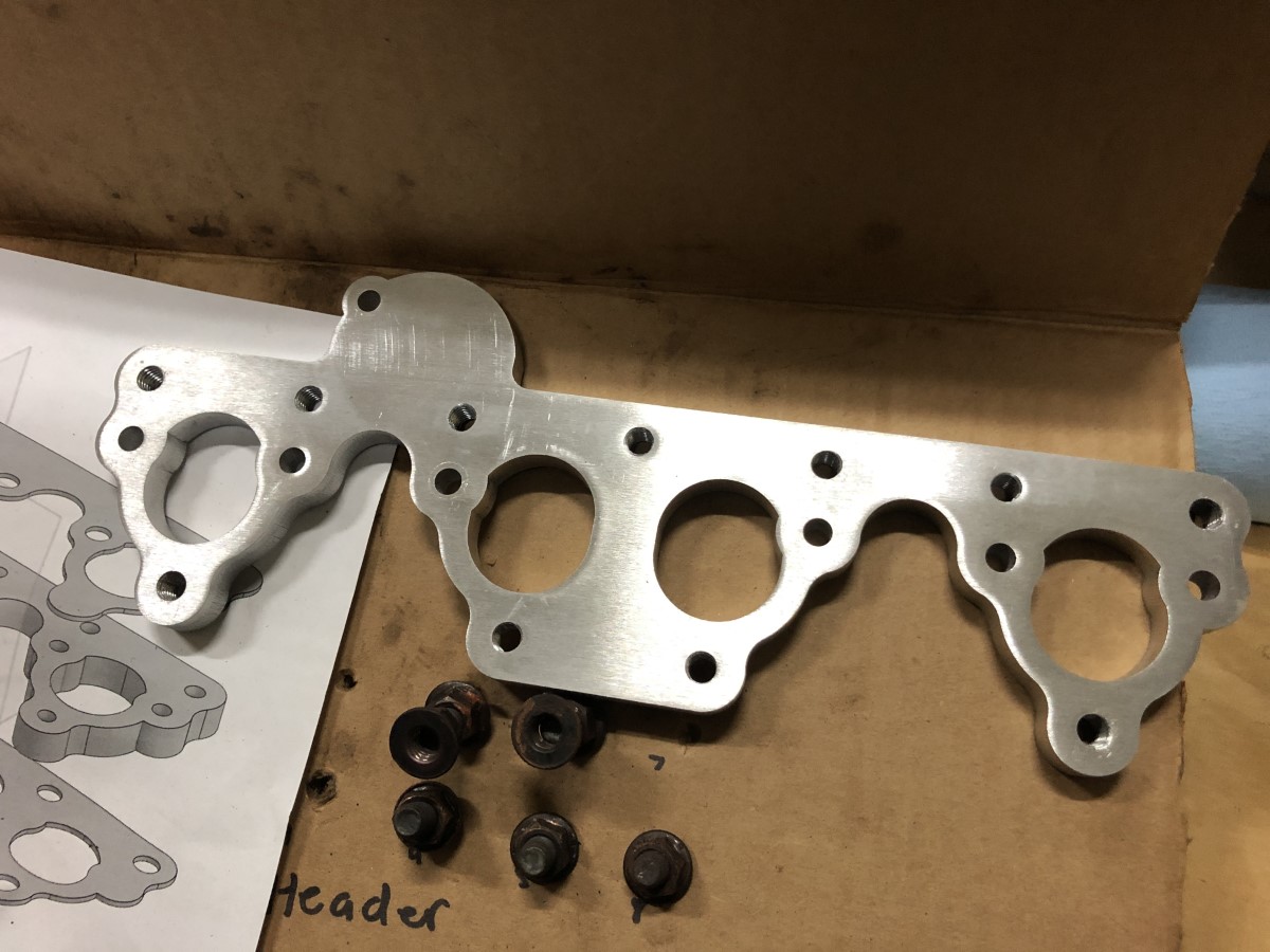
I know the issue, it’s a vacuum leak. How do you fix a vacuum leak? Seal it. Specifically from the intake manifold seals.
The easiest way to check this out is to take off the head and inspect my flanges and seals for warping. Knowing the manifold was bent, it’s not far off to think the flange was warped as well. Same goes for the seals that probably cause the warping from a leak, this caused a backfire in my carburetors. It was cool at first because I wanted to spit flames, then I found out that this was bad and not cool at all.
To fix this I had few options:
- Buy a new flange and gaskets to replace them
- Check for flatness, mill and reuse the same gasket
- Check for flatness, make my own gaskets and parts
I decided to make my own.
CAD, not the cardboard kind
It was a good excuse to finally learn more about CAD and machining. I learned graphic design and used graphic design in my projects before, so I figure I should jump into CAD. I used OnShape to design and SendCutSend, per recommendation from SuperFastMatt. Honestly, a lot of inspiration came from superfastmatt to make my own things.
Though I lack the experience and technical knowledge, I have stupidity and tenacity.
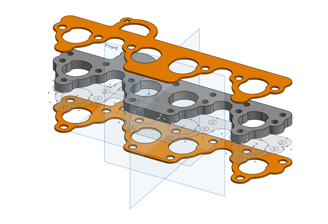
Making the gaskets and flange were very daunting
I first traced the gasket on a piece of paper then made arbitrary measurements with my cheap calipers and ruler. They were arbitrary because every measurement had +/- 2mm of variation. In machining, this is terrible. After a lot of google and youtube, I finally made something that looked identical to the part. I appended a part to cover my fifth intake hole since the original aftermarket part didn’t account for this.
Essentially, I made this part even better. Right?
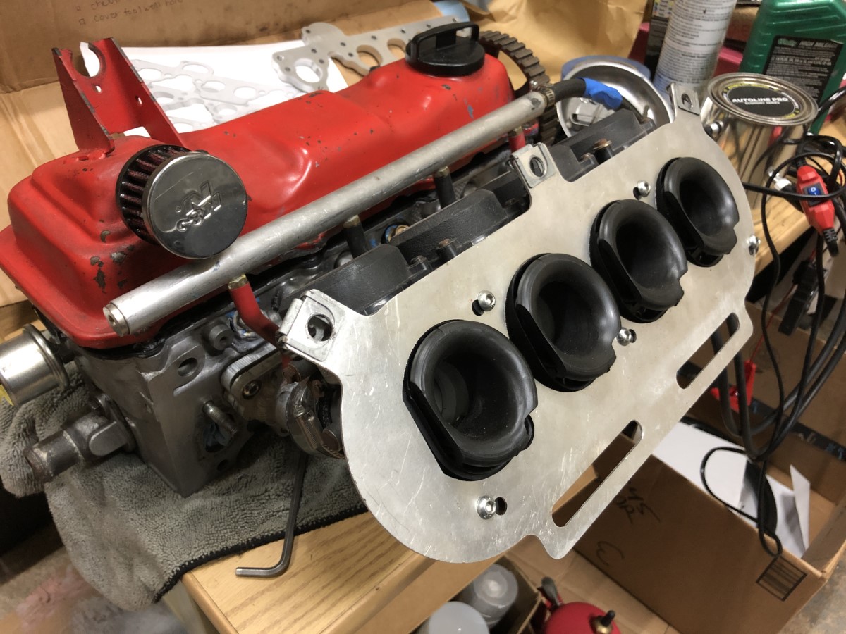
Testing with a smoke machine
My flange wasn’t correct so I ended up not using it. I refurbished the original flange instead.

My measurements made it not unusable but it’s a very good learning experience.

I might have been better off having a solid piece and drilling out the holes myself to match everything perfectly. Since I can’t use the new part to seal off everything, I had to make a small patch with body filler to the portion of the original flange to a part that I had made a small incision.
With the part patched, I sanded the aluminum piece on a long piece of wood with 400/800/1500 sandpaper to maintain the face squareness. It was not going to be a perfect flat surface, but I needed to remove the leftover material from my previous RTV sealing attempts. I tested the flatness with a machinist square and it was good enough!
I didn’t need to install the head yet, but I place it on there gingerly to test the flange sealing. I hooked up the smoke test in the same way as I did before with the new gaskes and used flange…
oh my goodness it worked.
3 days of learning and using cad paid off. In honesty, it probably saved me about $30. But that’s $30 I could use to buy whatever I want.!
This was a first for me, an actual DIY achievement for me. I designed my first bolt-on engine parts. Now, this wasn’t a performance part but it wasn’t particularly an easy part either. It took a lot of testing and trials and to see it come to fruition is something I can’t buy with bolt-on parts.

Looking Forward: Clean the engine, install the head
The block needs some cleaning from all that carbon, so I can get all of that done pretty easily. I’m SUPER stoked that I have a good chance of a succesful engine now, so in a couple weeks when everything is buttoned up, I’ll be up and running just in time for summer.
Cleaning block means using a green scrubby pad and being very careful not to get any particles in the holes. After cleaning the carbon, clean up the engine bay to prevent further contamination, lightly oil the cylinder bores, and reinstall the head!